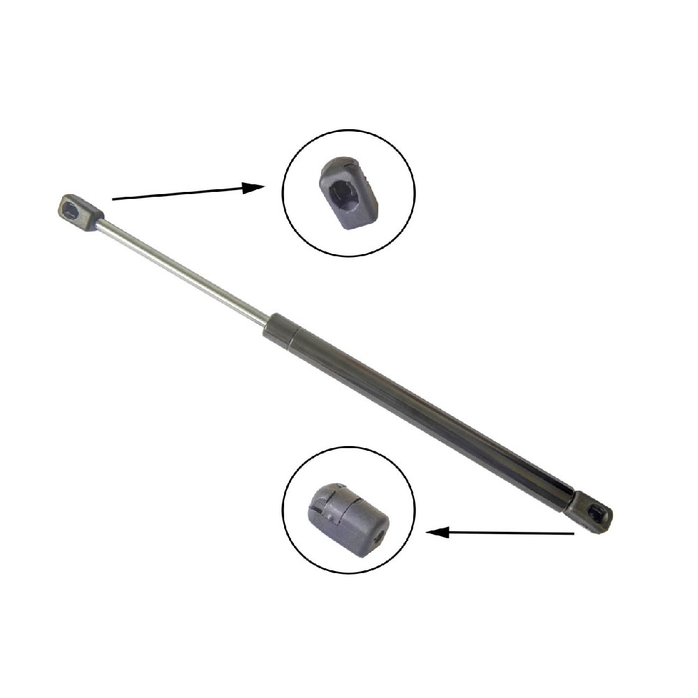
Elastic Locking Gas Spring
Elastic Locking Gas Spring’function is made possible by a special piston / valve system which creates a leak-proof separation between the two pressure chambers in the gas spring.


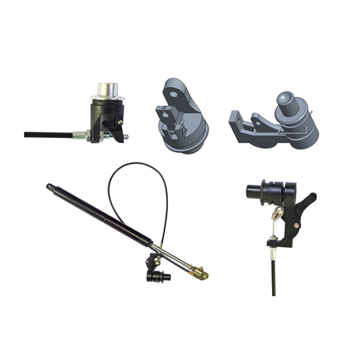
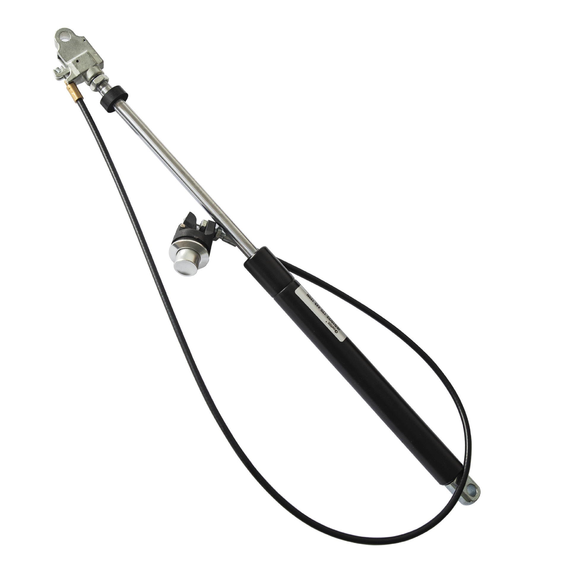
The locking function is made possible by a special piston / valve system which creates a leak-proof separation between the two pressure chambers in the gas spring. With the valve open, locking gas spring will provide force assist, ensuring user-friendly motion sequences due to its predefined damping characteristics. When the valve is closed, the gas spring will lock with a slight bounce in the desired position.
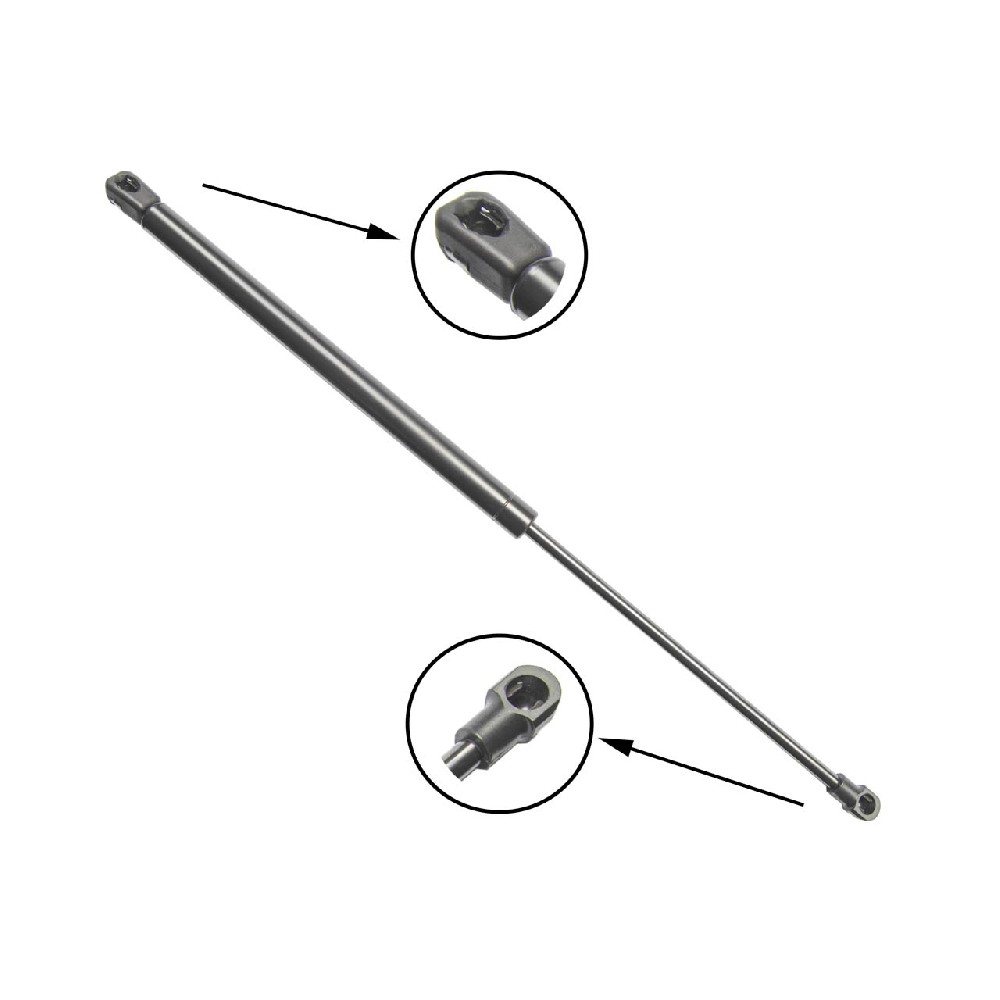
The standard locking gas spring is filled with gas and should be installed with the piston rod pointing down.
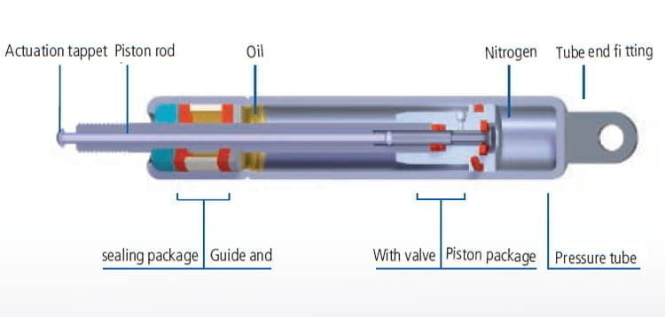
Elastic Locking Gas Springs Installation Dimensions

Specifications of Locking Gas Springs
| SPECIFICATION | FORCE(N) | STROKE(MM) | C-C LENGTH(MM) | CONNECTORS |
|---|---|---|---|---|
| JKQ10-22-20-146(O-N)600N | 600 | 20 | 146 | O-N |
| JKQ10-22-25-157(O-N)600N | 600 | 25 | 157 | O-N |
| JKQ10-22-30-168(O-N)600N | 600 | 30 | 168 | O-N |
| JKQ10-22-40-187(O-N)500N | 500 | 40 | 187 | O-N |
| JKQ10-22-60-228(O-N)500N | 500 | 60 | 228 | O-N |
| JKQ10-22-80-266(O-N)600N | 600 | 80 | 266 | O-N |
| JKQ10-22-100-307(O-N)600N | 600 | 100 | 307 | O-N |
| JKQ10-22-100-307(O-N)650N | 650 | 100 | 307 | O-N |
Application Cases:


